
Line following robotic vehicle using AT89S52
Line following robotic vehicle
It follow a black line automatically and it also turn it direction according to black line.In this article I have presented you an idea of Liner follower robot. How to make line follower robot using 8051 family micro controller.
CIRCUIT WORKING OF LINE FOLLOWER ROBOT:
Block diagram of line follower using 8051 micro controller is shown below. As I have clearly mentioned in block diagram. Two motors are used. One motor is attached with left Side of robot and another motor is attached with right Side of robot. Front wheel of Line follower robot is freely moving wheel. Motor driver IC is used to rotate both motors either clock wise or anti clock wise direction according to turning direction of Line follower robot. L293D motor driver IC is used as a motor driver IC AT89S52. Micro controller is used to give control signals to motor driver IC according to sensors output. IR Transmitter Receiver is used to sense black line. In case robot goes off from black line, respective sensor operate and micro controller sense its value and take control control actions by turn motors either clock wise or anti clock wise. Block diagram of line follower robot is shown below :

block diagram of line follower robot
IR_BLACK & WHITE DETECTOR SENSOR
I have used 2 sensors in this project. But you can also use more than 2 sensors according to width of black line to get better results of line follower robot..Circuit diagram of single sensor is shown below.


sensor circuit & pcb Layout for line follower robot
CIRCUIT DIAGRAM OF LINE FOLLOWER ROBOT USING AT89S52
Circuit diagram of line follower robot is shown below. here IR sensor Detect the Black & White color And Send information to micro controller it process the data and decide the vehicle is on track or not if it goes out of track then controller motor movement to get back on track .
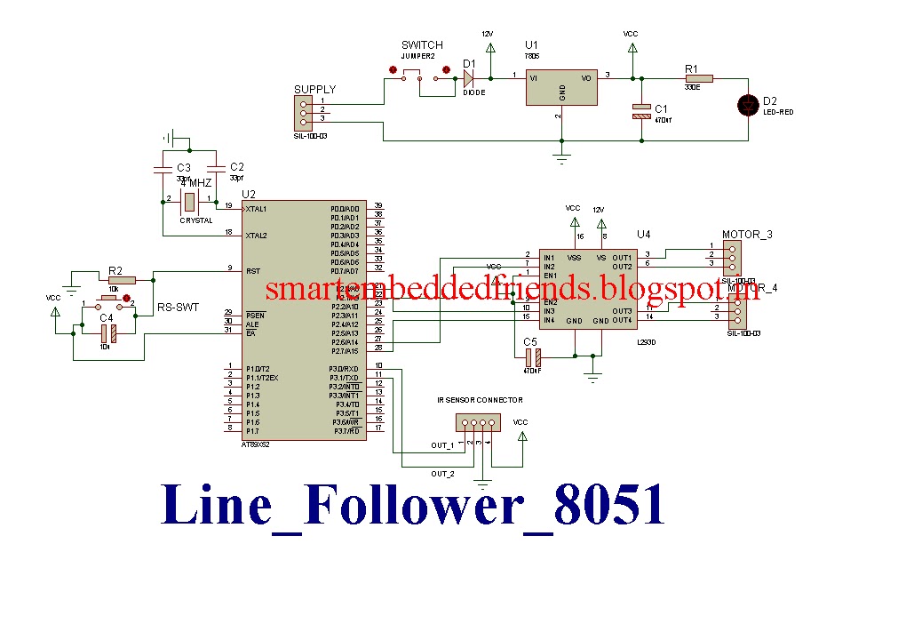

circuit diagram & pcb Layout of line follower robot using 8051 microcontroller
CODING FOR LINE FOLLOWER ROBOT
Code given below is written in Keil
// ***********************************************************
// Project: Line following robotic vehicle using AT89S52
// Author: SMart embedded Friends smartembeddedfriend@gmail.com
// Module description:
// ***********************************************************
#include<at89x52.h>
sbit SR=P3^0; //right sensor
sbit SL=P3^1; //left sensor
sbit IN1=P2^6; //Define Motor Connection Pin
sbit IN2=P2^1;
sbit IN3=P2^0;
sbit IN4=P2^7;
bit sl1=0,sr1=0; //Bit Use For Get Car On Track
void delay(unsigned int delay_ms);
void ir_Sensor_Process(); //Function To Process The IR Sensor Data
void main()
{
IN1=0;
IN2=0;
IN3=0;
IN4=0;
delay(1000);
SR=SL=1;
while(1)
{
ir_Sensor_Process(); //Process The IR sensor Data And Control The Car MOvement
}
}
void delay(unsigned int delay_ms)
{
unsigned int count,i;
for(count = 0;count<delay_ms;count++)
{
for(i = 0;i < 120;i++);
}
delay_ms--;
}
void ir_Sensor_Process()
{
if(SR==0 && SL==0)
{
IN1=0;
IN2=1;
IN3=1;
IN4=0;
}
if(SR==0 && SL==1)
{
IN1=0;
IN2=0;
IN3=1;
IN4=0;
sl1=1;
sr1=0;
}
if(SR==1 && SL==0)
{
IN1=0;
IN2=1;
IN3=0;
IN4=0;
sl1=0;
sr1=1;
}
if(SR==1 && SL==1)
{
IN1=0;
IN2=0;
IN3=0;
IN4=0;
delay(1000);
if(sl1==1&&sr1==0)
{
while(SR==1)
{
IN1=0;
IN2=0;
IN3=1;
IN4=0;
}
}
else if(sl1==0 && sr1==1)
{
while(SL==1)
{
IN1=0;
IN2=1;
IN3=0;
IN4=0;
}
}
}
}
kindly share it with your friends....
Click Here to Download Data Of Line following robotic Vehicle System Project

If you have benefited from this blog then please consider donation for this Blog, so that We can continue producing more free quality content for everyone. Even a small contribution is much appreciated. Thanks!


No comments:
Post a Comment