DTMF Controlled Robotic Vehicle Project
Previously we have robotic vehicles use RF circuits, which
have the drawbacks of limited working range, limited control and limited
frequency range. To solve this problem we provides DTMF based robotic vehicle system It provides the
advantages of robotic control, intrusion free controllers and
also robust control, minimal interference and a large working range.
This system involves four different phases: perception,
action, processing and detection. In the perception stage if the mobile
attached to the vehicle receives a call, then the pressing key on the mobile
decodes the generated DTMF tone. Then, the decoder chip receives the audio
signal from the mobile, and then converts the DTMF tone into a binary code,
which is then fed to the microcontroller.
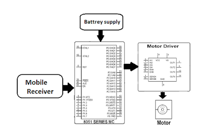
Block
diagram:
The major building blocks are microcontroller, mobile, DTMF
Decoder and DC-Motor-driver circuit. The entire system works and is activated
by the mobile that makes a call to the mobile attached to the robotic vehicle. If
any button is pressed, then DTMF (dual tone multi frequency) receives the input signal from cell phone
and decode it. Then generates 4-bit-digital output of the 8051 microcontroller.
Microcontroller depends upon the code which is generated by
the DTMF decoder to move the rover right or left and forward or backward by
rotating both DC motors. The DC motor driver receives activating signals from
the microcontroller in terms of low or high logic, then it amplifies and
rotates two motors in both directions. The output of the microcontroller is not
enough to drive the DC motors, so current drivers are necessary for motor
rotation.
Hardware requirements:
- AT89c51 Microcontroller
- Mobile Phone
- DTMF Decoder IC MT8870
- DC Motor
- Power Supply
- · MC Programming Language: Embedded C
- · Keil version IDE
- · Proteus For Circuit & PCB Designs


