Showing posts with label Device Control. Show all posts

Password Based Load Control System

Password Based Load Control System


Nowadays, electrical accidents to the line man are increasing, while repairing the electrical lines due to miscommunication between the maintenance staff & the electric substation staff. During the electrical fault or short circuit, the power network will suffer from a high stress of fault current in them which may harm the equipment permanently.
To overcome this problem, we introduces password based load control system which is arranged in such a way that maintenance staff or line man has to enter the password to ON/OFF the electrical line. Separate passwords are allocated for every electrical line that access by authorized person only. Now, if there is any mistake in the electrical line then the line man will switch off the power supply to the line by entering password and comfortably repair the electrical line.
Block diagram:
Block Diagram Password Based Load Control System

The main component in the circuit is 8051 microcontroller. A 4×4 matrix keypad is used to enter the password. The password which is entered is compared with the predefined password stored in ROM of microcontroller. If entered password is correct, then the corresponding electrical line is turned ON or OFF and display line or load status on LCD. If the password is wrong, then display “wrong password” on the LCD.
In this project a separate password is provided to each electrical line. Activation and deactivation of the line (circuit breaker) is indicated by the load (Light Bulbs).
Hardware requirements:
·       8051 microcontroller
·       keypad
·       Voltage regulator
·       LCD
·       Power supply
·       Relay driver
·       Relays
·       Lamps


Software requirements:
  •           MC Programming Language: Embedded C
  •           Keil version IDE
  •           Proteus For Circuit & PCB Design


Download Abstract Password Based Load Control System


Android Based Programmable Sequential Load Operation Controlled 8051 Microcontroller

Android Based Programmable Sequential Load Operation Controlled System Based On 8051 Microcontroller


We know that in industries, loads are distributed over large distances, At present, they are physically controlled which makes it complex to organize the lighting with the particular scene and it is not convenient to operate all those equipment time to time and it is also time to consume.For distant controlling and monitoring of different loads and by means of efficient power usage we are introducing android based programmable sequential load operation controlled system.
in this we can switch the industrial loads using programmable device and android application for sequential operation. Remote operation is achieved by any smart phone with android OS upon a GUI based touch operation.In industries, there are many tasks are carried out which requires some repeated operation in various orders and time intervals sothe objective of this project is to facilitate the loads, that are to be operated either manually or automatically, by using remote Android mobile
Block diagram:

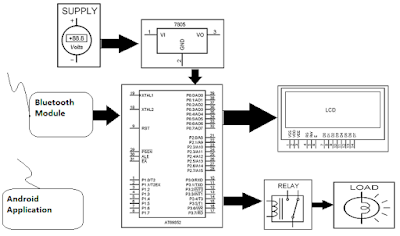
Block Diagram Android Based Programmable Sequential Load Operation Controlled 8051 Microcontroller

The project is designed to operate loads using relays interfaced to a 8051 microcontroller through remotely operated commands to it by touch screen based user friendly GUI on any smart phone with Android applicationsto control the system initiates the operation of the circuit. This entire system works on Bluetooth that is attached to the circuit.
Microcontroller is programmed in such a way that the loads a can be operated in three modes: Set mode, Auto mode and Manual mode.
In set mode, through timers, the machinery works based on input time set by the user where as in auto mode it works on default time settings and finally in the manual mode it functions while respective switches are pressed depending on the user’s need and flexibility Whenever the corresponding button to auto-mode is pressed in the Android phone, the microcontroller senses that signal and correspondingly switches the loads set by the user. All the modes and status of loads are displayed on an LCD.

Hardware requirements:
·       8051 microcontroller
·       LCD
·       Voltage regulator
·       Bluetooth device
·       Power supply
·       Android application
·       Relay driver and relays

Software requirements:

·      MC programming language: Embedded C

·      Keil  version IDE
·      Android Application
·       Proteus For Circuit & PCB Design


Download Abstract Android Based Programmable Sequential Load Operation Controlled 8051 Microcontroller


SCADA (SUPERVISORY CONTROL & DATA ACQUISITION) For Remote Industry Based On 8051 Microcontroller

SCADA  (SUPERVISORY CONTROL & DATA ACQUISITION) For Remote Industry Based On 8051 Microcontroller


SCADAsystems are mostly used in industry for supervisory control and data acquisition of industrial process application as they are simple, robust, and reliable in use. This process can be industrial and infrastructural, with the further use of electronic and the SCADA systems are used in large scale industrial plant automation where monitoring andcontrolling all the process at a time manually is not possible. It provides an efficient tool to monitor and control equipment in manufacturing processes
The main goal of the supervisory control of data acquisition for remote industry is to process the real-time data obtaining under supervisory control for a large-scale remote industrial environment.
Block diagram:
Block Diagram SCADA  (SUPERVISORY CONTROL & DATA ACQUISITION) For Remote Industry Based On 8051 Microcontroller


Here temperature sensors are interfaced to the 8051 micro-controller Information gathered from the temperature sensors are always sent to the microcontroller which is thus associated with a PC.On the front end, “DAQ System” (software) loaded in the computer which takes these values and displays them on its front panel, and also logs then in the database. We can set parameters like set point, low limit and high limits on the computer screen.
When temperature of a sensor goes above the set point the micro-controller sends a command to the corresponding relay. The heaters are connected through relay contacts (corresponding to their sensors) are turned OFF are available for generating an AV alarm on the PC in the event of system failure. Hence, processes at hazardous area can be controlled accurately and better safety using Supervisory Control and Data Acquisition. Adapting such a technology will save both money and time.
Hardware requirements:
·       8051 microcontroller
·       Relay Driver IC
·       MAX232 IC
·       IC Socket
·       LM35 Temperature Sensor
·       DB9 Connectors
·       LED
·       Relays
·       Lamps
·       Power supply

Software requirements:
  • MC Programming Language: embedded C
  • Keil  version IDE
  • Proteus For Circuit & PCB Design


Block Diagram SCADA  (SUPERVISORY CONTROL & DATA ACQUISITION) For Remote Industry Based On 8051 Microcontroller


RF Based Home Automation System using 8051 Based Microcontroller

RF Based Home Automation System using 8051 Based Microcontroller


In today’s highly developing world most of  peoples wantstheir homes areautomated as per increased level of affordability,simplicity  and comfort through the integration of home appliances with smart phone and tablet connectivity.Home Automation system that controls various home appliances such as a fan, bulb, AC, TVetc. with RF remote controller..
So here we introduce Home automation system which is developed to automate the use of conventional lighting mechanism (wall switches)in house by using RF controlled remote that sends ON/OFF signals to microcontroller.

Block diagram:-
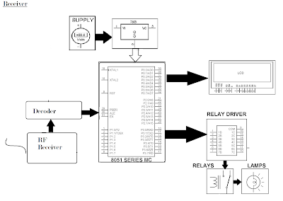
Block Diagram RF Based Home Automation System using 8051 Based Microcontroller

Block Diagram RF Based Home Automation System using 8051 Based Microcontroller


The system is mainly based on RF modules is the combination of RF transmitter and RF receiver which used as remote to controlled the system. So user can simply give the commands through the RF remote which are received by RF transmitter then it will sends to the microcontroller and then microcontroller will handle the particular load.
The micro controller is programmed in a way that whenever the command is given through the RF remote for driving the appliances on and off, it communicates with the relay circuit. Suppose if u want ON the load 1 then you simply press the button 1 on RF remote then this signal will received by transmitter and send to microcontroller then it will ON the load 1 and massage will be displaying on LCD.

Hardware Specifications:-

·        8051 series Microcontroller
  • LED Display
  • Power supply
  • Relays and connectors
  • LCD
  • HT12D & HT12E
  • RF modules 434mhz
Software Specifications:-
  • MC Programming Language: embedded C
  • Keil  version IDE
  • Proteus For Circuit & PCB Design


Download Abstract RF Based Home Automation System using 8051 Based Microcontroller